
-
Introduction
In support of the LM4562 opamp, National Semiconductor published Application Note AN-1651, Keeping Up with the Expanding Demands of High-Performance Audio. (Link updated 8/4/20). The author, Joe Curcio, showed designs for two phonostages and an electrostatic headphone driver. I built the second phonostage design, a two stage moving coil preamp with split active/passive RIAA equalization and a DC-nulling servo.
Here’s the schematic from the application note, complete with original errors. Mine is slightly different, as described later.

-
Two Versions
I built two versions of the circuit.
The first one was done point-to-point, aka “deadbug” style, aka “Manhattan” style. In this technique, a copper-clad board is used as both a platform for the parts and the ground plane. Some components are glued to the board. Leads are soldered directly to each other. Some components are held airborne by their leads and the leads of the other components they’re soldered to.
This version had problems with a bit of RF pickup. I helped a friend build a copy of mine and his produced mysterious intermittent thumping noises. We could never find the cause, though it was probably an elusive cold joint.
For the second version, I designed a PCB and had it made by expresspcb.com. My PCB still had RF pickup problems. My friend built the PCB version too and his has fewer RF issues than mine. At least the thumps are gone.
-
RF Pickup
In an attempt to reduce susceptibility to RF pickup, the circuit was modified by
- adding RF gain compensation caps around U1 and U2
- adding ferrite beads on the inputs
While reading Jung’s 1995 voltage regulator articles, I found an interview with Allen Burdick (Benchmark Media Systems) in TAA 1995/4 that discussed RF gain in op amps and distortion. He has a criteria to leave at least 20db of unused gain at all frequencies in a gain circuit so there is enough open loop gain available for negative feedback to correct for any RF-induced errors in the circuit. This is accomplished by a gain compensation cap across the feedback resistor that creates a low pass filter. The pole sets the upper frequency below which the gain is flat and above which the gain curve decreases, roughly paralleling the gain bandwidth curve 20db above it.
In my preamp, the HF rolloff for the two gain stages combined is about 0.06db at 20kHz, 0.23db at 30kHz, and 3db at 100kHz. The compensation cap values were determined graphically using a plot of the OPA1611’s gain bandwidth, and then verified by modeling the filters in SPICE and combining them in a spreadsheet.
Even with these changes, RF was still a problem, so I have since tried
- enclosing the board in a box made of Permalloy
- adding RF filtering on the power supply input
There is still a little RF pickup that can be heard as impulse noise patterns at random. I live very close to a cell phone tower. The noise can be conjured at will by bring a cordless phone or a cell phone close to the phonostage. My friend’s build doesn’t have this problem, at least with ambient RF. I plan to eliminate two more possible causes: replacing the power rail circuitry U4/U5 with one of my Hubble regulators, and adding load isolator filters on the outputs.
-
Component Selection and Noise
Since I was so satisfied with the sound of the deadbug version, I decided to go for the lowest noise and distortion that I was willing to pay for with the PCB version. The RIAA caps are boutique polystyrene caps, but not too expensive. The cost of available Teflon caps was too high for me to stomach. The cap tolerance was not that great, so a friend measured them on a lab meter and I recalculated the RIAA resistors for the same network response as the original design.
The noise of the deadbug build was too high for my taste: With focus, I could barely make out the noise signature of the preamp below the surface noise level of the vinyl when playing back low level passages. I purchased and built Jim Hagerman’s Piccolo MC headamp board and put this in front of the AN1651/Curcio after dropping the gain of the first stage. This was a failed experiment as there was no noticeable change in the noise level.
I improved the noise performance by about 8db (on paper) by scaling down the resistors in the input stage by about 4.7x and switching to the OPA1611 opamp. The OPA1611 opamp has better noise specs than the LM4562, so I used it for U1, U2, and U3. This change alone should improve the noise in U1 by 3db. Rescaling the resistors and caps in the first stage reduced the current noise through the resistors for another 5db noise improvement. This required changing C4 from 100nF to 470nF, which is a pretty large cap in polystyrene. Because the lower value resistors could have loaded the first stage too heavily, I did some current calculations. The original network requires 45µA from U1, while the scaled network requires about 200µA, well below the maximum output current for the OPA1611. Listening confirms that there is a very worthwhile improvement in the noise, but the precise reduction is not known.
A friend suggested using IRC tantalum nitride thin film resistors because of their non-magnetic materials and construction and excellent performance. They’re rather pricey at $0.70 each from Mouser in the 1206 SMD package, but I am glad I used them.
You many find this spreadsheet I made useful for calculating the noise of an inverting opamp stage and for comparing different opamps.
-
Sound
My previous phono preamp/reference was the Yamaha C-2a. The AN1651/Curcio preamp has no apparent difference in tonal balance. The highs are much cleaner, but neither higher nor lower in level. The Yamaha had a significant amount of power supply noise and hash, AC (power line) buzz and hum, as well as component noise. This phono preamp is vastly cleaner sounding in these areas.
Ticks and pops are much less apparent. No or less ringing, faster recovery? Several huge pops that I know and love (!) on some records aren’t nearly as obnoxious as they used to be. I always thought if ticks and pops are less prominent it meant that the cartridge was not extracting enough low level signal. But the cartridge didn’t change, so the problem was related to the Yamaha’s electronics.
Certain sibilant and hashy torture tracks I use for testing are very much cleaner if not completely undistorted. These have female voice, hand claps, loud continuous snares, etc. They sounded like sandpaper when not reproduced right.
Whether because of the lower inherent noise or less distortion due to layout and parts, I hear more and clearer low level information. Sounds sound more real.
-
Photo Gallery
-

- Schematic for AN1651/Curcio Phono Preamp with Active/Passive EQ
-
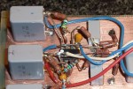
- AN1651/Curcio Phono Preamp (deadbug detail)
-
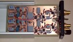
- AN1651/Curcio Phono Preamp (deadbug in box)
-
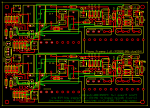
- AN1651/Curcio Phono Preamp (PCB design)
-

- AN1651/Curcio Phono Preamp (PCB stuffed)
-

- AN1651/Curcio Phono Preamp (PCB in box)
-


Well, I am glad that Eric finally got this site up and running! I am the friend mentioned here with the “other” Curcio. After initially building this via copper board and point to point to soldering, it’s definitely nice that I finally pushed Eric into designing a board for it! My first iteration of the Curcio, with much help from Eric, sounded great, however, there was this intermittent “thump” that occured once or twice each listening session. Try as I and Eric may, we couldn’t figure out the problem. So, after months and countless go at resolving this issue, I finally started the ball rolling, sort of speak, that resulted in Eric’s Curcio boards!
In my current version, instead of using surface mount resistors and opamps (as in Eric’s), I parted out the first iteration and reused what I could. I used Vishay/Dale CMF resistors, and the nude Vishay TX2353 on U1, U2 and U3. I also used the Jantzen Superior Caps on C4 and C5. Anyways, I think the Curcio sounds wonderful! I am glad and thankful for Eric’s work and help.
Thanks Eric!
Tuan
Hi, do you have any boards available or can you send the files to have one made?
Thanks for doing this great work!
Though I looked for it, I couldn’t find the specs I was looking for: S/N, frequency response (3db), % THD.
Your phono amp looks like what I’m looking for. I’m dreaming of a low-noise wide-bandwidth low-distortion amplifier which I can bury in my Thorens TD-125 rebuild.
My cartdridge for now is the Grado Gold, my system amp is a low noise Denon AVR 3806 (i think), which in Direct mode has a -115db S/N ratio, 50khz+ bandpass (approx).
I’d run your amp on a rechargeable battery which would I would recharge when the amp is not in use.
I’d like phono (female) for input and output.
Please quote time and money.
Thanks and Aloha!
Bill Hill
PS: Is the Banner1 photo a picture of the lighthouse at Point Reye’s National Seashore? If so, I have a story for you…(smile)
Your thumps are (were?) due to popcorn noise in the LM49710. I built a phono preamp using the dual version of this op amp and it has the same problem. It happened on one but not another because it’s due to the manufacturing process and may or may not occur on any given op amp. The only solution is to individually test op amps before the build or use a better op amp for at least the first amplification stage.
Also, IMHO this is not a very good phono stage design.
I think you may have offered some positive suggestions as to what would improve the design rather than just saying that it’s not very good. What don’t you like about it?
A well documented article. I commend your hard work.
Some comments . . . I believe that this chip is very fast and is susceptible to RF issues, it slews at 20 volts per µSecond and has a GBW of 55 million. So, the first stage at a gain of 16 would have an upper frequency F3 at 3.4 MHz.and the second stage is also up around 3MHz, and this would need some attention. The power supply rail conditioning looks like the high-level,shot noise from the 1 mega-ohm resistors is amplified 9.6 times and injected into the plus and minus rail supply for the 49710 audio amps. I do see the 1 µF caps to help filter it back out. Hmmmmm. I would have to build up that conditioning circuit and measure the ac noise to see how much improvement is made.
The DC servo circuit to reduce the offset voltage is good.
Definitely a circuit layout that needs 0.1µF caps right on the IC power pins. Overall, I feel the 49710 is too much horsepower for this application. At least put some bypass caps (pF) across all the audio-stage feedback resistors to filter off everything above 100 KHz or so.
Just some ideas, hope someone finds them helpful.
Your analysis of the supply rail noise is incorrect. The DC current flowing through the 1 mega-ohm resistor is only the input bias of the 49710 (10nA) and thus the shot noise is in femto-amps which is unlikely to produce any meaningful signal on the 0.1uF decoupling capacitor. It is novel, in audiophile circles, to see someone worrying about slew rates being too high!
In defense of audiophiles, the application note mentions demands on slew rate in section 2 but doesn’t elaborate. We’re in good company with Mr. Curcio!
It’s worth noting that the original design is based round a MM cartridge – hence the 47K input resistor. Such a cartridge would have an source resistance of 500-1000 ohms and of In this application the resistor noise in R7 is relatively insignificant. However, if the circuit is to be used with a low impedance MC cartridge, then a reduction in the component values in the first gain stage is useful. However it would actually be easier to ‘swap’ the two gain stages as the second stage has a much lower impedance feedback loop.
I questioned the 47K input resistor at first. But the design is definitely for moving coil cartridges: the note refers to low output moving coils cartridges throughout, the gain is around 70dB (typical for MC), and Section 3.3 advises trimming the input impedance. He suggests to solder loading resistors across the input connector, and to try different values starting with the cartridge manufacturer’s spec or 100R.
The 40 year old Yamaha C-2a has a pair of RCA jacks beside the phono inputs for capacitive loading plugs and a series of resistor values selected by a switch on the front panel.
It’s been so long since I built this that I don’t recall what loading I settled on.
Hi Bard,
Okay, 6+ years later– sorry. You’re right, some elaboration of my comment is due…
First, I don’t like the LME49710 and similar because of the popcorn noise. See this TI support page where, at the end, two TI guys punt: https://e2e.ti.com/support/audio/f/6/t/415907?LM4562-LME49720-low-frequency-noise . Especially see the plot from Wayne Kirkwood.
Next, U4 and U5 have limited slew rate and output current. The transient response on the data sheet looks okay but it’s only a voltage change– no load current change is given except to charge the 100pF, and that’s where you need a true “rail.”
1uF capacitors at the outputs of U4 and U5 don’t provide much reserve current. Also overshoot of 16% is spec’d for C(load) = 100pF. It’s likely to be marginally stable when directly driving 1uF and will probably ring when hit with a load current step. A small damping resistor can be added in series with the outputs but that increases output impedance. PSRR for LM49710 increases pretty rapidly above 1kHz so noise or higher frequency hash on the +-15V rails can get to U1/2/3.
U4 and U5 get 15V power rails and 13.8V DC input. This is outside the max common mode input range, and even outside the typical values for positive and negative sides. So whatever regulation you get is most likely the op amp’s output transistor pushing as hard as it can to move the inverting input to match the non-inverting input. Raising the power rails to +-16V and keeping Vin at 13.8V will fix this.
A benefit of the U4/U5 regulation is when AC mains voltage sags you don’t lose regulation, you only lose dynamic range.
Also you could operate U5 as a unity gain inverter and feed U4 output to it to get the negative rail and save a few components. But you lose the isolation between plus and minus rails.
U1/2/3 amplifiers operate as non-inverting, so their CMRR is not as good as it would be when used as inverters. I don’t see anything in the data sheet to say if the CMRR measurements are for inverting or non. Likely it’s inverting because marketing gets the last word. Yanking the insides of the op amp around can also add distortion, whereas inverting mode keeps its inputs near zero by moving current instead of voltage.
DC nulling amplifier U3 may be marginally stable for the same reason as U4/U5. It also passes thermal noise from two 1MegOhm resistors back to a gain of 18 amplifier to the output, although maybe (in my hasty analysis) R12 shunts it to ground?
So to summarize my own preferences, I prefer dedicated high performance voltage regulation (disclaimer– I am president of Belleson LLC). Use better op amps. Follow Williams’s rule– always invert, except when you can’t. Considering this is a moving coil preamp with low signal levels, power supply transient response to load current changes is probably not an issue, but stability could be.